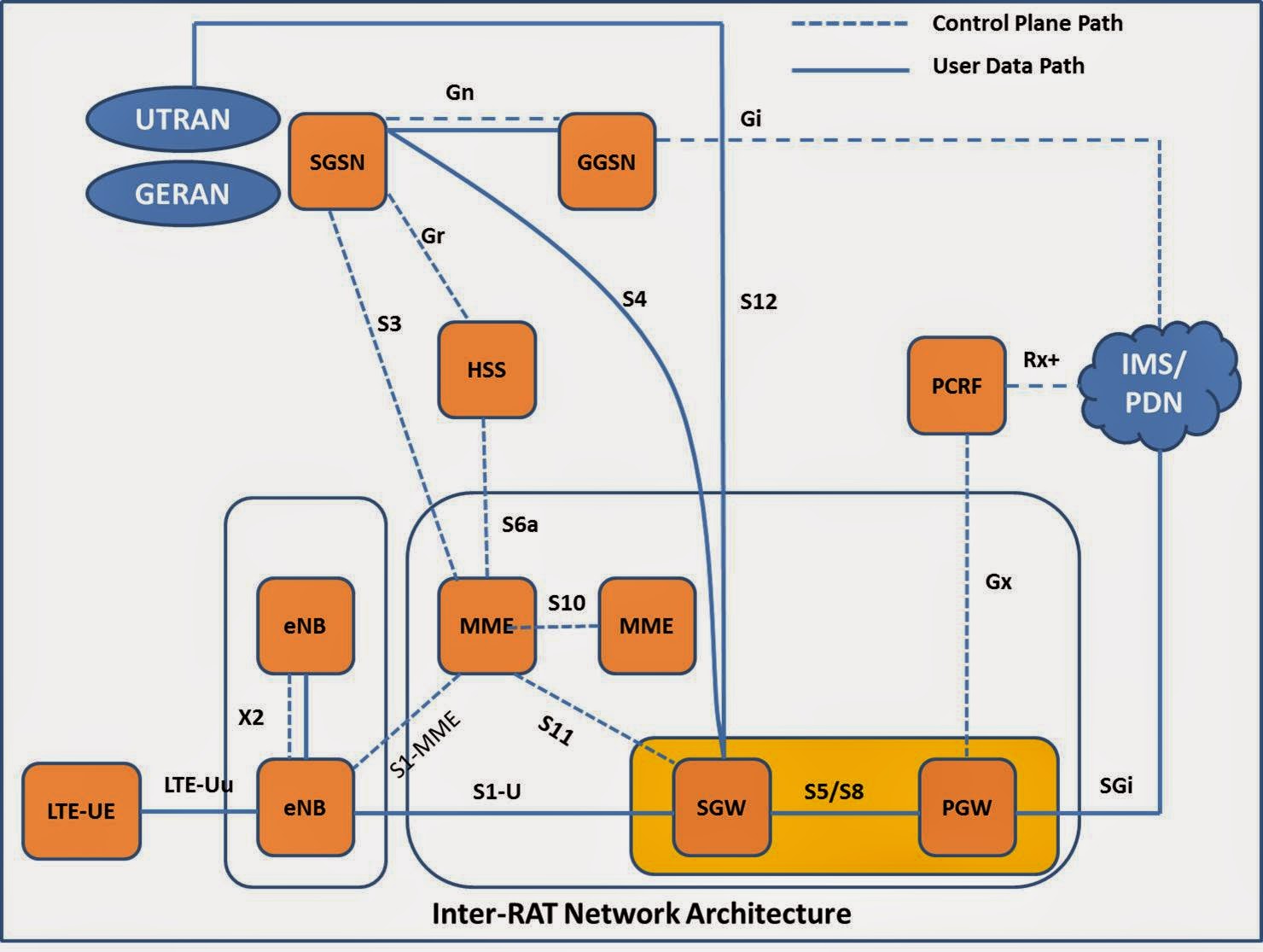
LTE Network
Architecture:
Ø
UE: User Equipment
Ø
E-UTRAN: Evolved UMTS Terrestrial Radio Access
Network.
Ø
eNobeB (eNB): Evolved NodeB
Ø
MME: Mobile Management Entity
Ø
EPC: Evolved Packet Core
Ø
SGW: Serving Gate Way
Ø
PGW: Packet Gate way
Ø
HSS: Home Subscriber Server
Ø
PCRF: Policy & Charging Rule Function
E-UTRAN
(Evolved UMTS Terrestrial Radio Access Network)
ü
It supports the LTE air Interface.
ü
EUTRAN consists of eNB’s.
ü
It provides user plane (PDCP/RLC/MAC/PHY) and
control plane (RRC) protocol terminations towards the UE.
ü
The eNB’s are interconnected to each other via
X2 interface.
ü
The eNB’s are connected to MME via S1-MME
interface.
ü
The eNB’s are connected to SGW via S1-U
Interface.
ü
The eNB’s support Many to many relation with
MME/SGW.
eNodeB Functions:
ü
Radio Resource Management:
•Radio Bearer Control (i.e. the
establishment, maintenance and release of Radio Bearers).
•Radio Admission Control, to admit or
reject the establishment requests for new radio bearers.
•Connection Mobility Control, concerned
with the management of radio resources in connection with idle or connected
mode mobility.
•Dynamic resource allocation for UEs in
both uplink and downlink (also called packet scheduling).
ü
IP header compression and encryption of user
data stream.
ü
Selection of an MME at Initial UE attach when no
routing to an MME can be determined from the information provided by the UE
ü
Routing of User Plane data towards Serving
Gateway.
ü
Scheduling and transmission of paging messages
(originated from the MME).
ü
Scheduling and transmission of broadcast
information (originated from the MME or O&M).
ü
Measurement and measurement reporting
configuration for mobility and scheduling.
MME (Mobility
Management Entity):
ü
It is a pure signaling entity inside the EPC.
ü
MME is connected to eNB via S1-MME interface.
ü
MME controls one or several SGWs via S11
interface
ü
MME is connected to HSS via S6a interface.
ü
MME can be connected to SGSN’s via S3 interface.
ü
MME are interconnected via S10 interface.
ü
Manages mobility, UE Identities and security
parameters.
MME Functions:
ü
Non Access Stratum (NAS) signaling and security
The NAS protocol is used on the control plane between the UE and the core network, the MME (Mobility Management Entity). The NAS layer is handling mobility related functions between the UE and the core network, like attach and tracking area update, authentication and security. It is also responsible for establishing and maintaining IP connectivity between the UE and the core network.
ü
Inter CN node signaling and SGSN selection for
mobility between 3GPP access networks.
ü
Idle mode UE reachability (including control and
execution of paging retransmission)
ü
Tracking Area list management (for UE in idle
and active mode)
ü
PDN GW and Serving GW selection
ü
MME selection for handovers with MME change
ü
Roaming (terminating S6a towards home HSS)
ü
User authentication and authorization support
ü
Bearer management functions including dedicated
bearer establishment
ü
Lawful Interception of signaling traffic.
SGW (Serving Gateway): The Serving Gateway is the node that
terminates the interface towards EUTRAN. For each UE associated with the EPS,
at a given point of time, there is one single Serving Gateway.
ü
It manages the user data path (EPS Bearers)
within EPC.
ü
It transmits and receives packet data to and
from eNB via S1-U interface.
ü
SGW is controlled by one or more MMEs via S11
interface
ü
For interworking to other 3GPP RATs, it can be
connected to SGSN via S4 interface or to
the RNC via S12 interface (when Direct
Tunnel feature is implemented).
ü
It relays the packet data to or from the PDN
gateway via S5/S8 interface.
SGW Functions:
ü
Packet Routing and Forwarding.
ü
The local Mobility Anchor point for inter-eNB
handover
ü
Sending of one or more "end marker" to
the source eNodeB, source SGSN or source RNC immediately after switching the
path during inter-eNodeB and inter-RAT handover, especially to assist the
reordering function in eNodeB.
ü
E-UTRAN idle mode downlink packet buffering and
initiation of network triggered service request procedure
ü
Mobility anchoring for inter-3GPP mobility
(terminating S4 and relaying the traffic between 2G/3G system and PDN GW).
ü
Lawful Interception
ü
Transport level packet marking in the uplink and
the downlink, e.g. setting the DiffServ Code Point, based on the QCI of the
associated EPS bearer
ü
Accounting for inter-operator charging. For GTP*-based
S5/S8, the Serving GW generates accounting data per UE and bearer.
ü
Interfacing OFCS* according to charging
principles
ü
Packet Filtering with TFT*
GTP = GPRS Tunneling Protocol
OFCS = Off-Line Charging System
TFT = Traffic Flow Templete.
PGW (PDN Gateway):
The PGW is the node that terminates the SGi interface towards the PDN. If a UE
is accessing multiple PDNs, there may be more than one PGW for that UE. The PGW
provides connectivity to the UE to external packet data networks by being the
point of exit and entry of traffic for the UE. The PGW performs policy
enforcement, packet filtering for each user, charging support, lawful
Interception and packet screening.
ü
PGW provides connectivity towards PDN (eg.
Company intranet, internet, and IMS) via SGi Interface.
ü
It is comparable to GGSN
ü
A major functionality provided by a PGW is the
QoS coordination between the external PDN and EPC.
ü
PGW can be connected to a PCRF via Gx Interface.
ü
In Local Breakout scenario, PGW transmits and
receives packet data from SGW in the same PLMN via S5 interface.
PGW Functions:
ü
Per-user based packet filtering (by e.g. deep
packet inspection).
ü
Lawful Interception
ü
UE IP address allocation
ü
Transport level packet marking in the uplink and
downlink, e.g. setting the DiffServ Code Point, based on the QCI of the
associated EPS bearer.
ü
Accounting for inter-operator charging.
ü
UL and DL service level charging (e.g. based on
SDFs defined by the PCRF, or based on deep packet inspection defined by local
policy).
ü
UL and DL rate enforcement based on APN-AMBR
(e.g. by rate policing/shaping per aggregate of traffic of all SDFs of the same
APN that are associated with Non-GBR QCIs)
ü
Packet screening (firewall)
ü
Policy enforcement (gating and rate enforcement)
ü
Mobility anchor for mobility between 3GPP access
systems and non-3GPP access systems. This is sometimes referred to as the SAE
Anchor function.
PCRF (Policy &
Charging Rule Function)
ü
PCRF is responsible for negotiating QoS policy
and charging policy on a per flow basis.
ü
The PCRF major functionality is the QoS
coordination between the external PDN & EPC.
ü
The PCRF is connected via Rx+ interface to the
external Data network (PDN)
ü
This function can be used to check and modify
the QoS associated with SAE bearer setup
from SAE or to request the setup of a SAE bearer from the PDN.
ü
This QoS management resembles the policy and
charging control framework introduced for IMS with UMTS.
PCRF Functions:
ü
Binding mechanism, associates a service data
flow to the EPS bearer deemed to transport the service data flow
ü
Reporting, Credit Management, Event Trigger,
Termination Action.
ü
Service (data flow) prioritisation and conflict
handling
ü
Standardised QoS characteristics
ü
Handling of packet filters.
ü
In non-roaming scenario, there is only a single
PCRF in the HPLMN associated with one UE's IP-CAN session. The PCRF terminates
the Gx, Gxc and Gxa interfaces.
HSS ( Home Server
Subscriber):
ü
It was first appeared in 3GPP Release 5 as part of
IP Multimedia Subsystem (IMS)
ü
It has similar function to HLR (Home Location
Register) and AuC (Authentication Center) in GSM/UMTS network.
ü
In LTE/EPC, the HSS stores data for mobility and
service handling per subscriber.
ü
HSS utilizes DIAMETER protocol to support
LTE/EPC.
ü
The HSS can be accessed by MME via S6a
interface.
For EPS, the HSS data
may contain:
ü
IMSI
(International Mobile Subscriber Identity)
ü
IMEI
(International Mobile Station Equipment Identity)
ü
MME Address
ü
EPS subscribed charging characteristics (e.g.
prepaid, normal, flat-rate etc.)
ü
Subscribed UE-AMBR. It determines Aggregate
Maximum Bit Rate per subscriber
ü
PDN Address
ü
APN (Access Point Name)
ü
EPS Subscriber QoS profile, etc.